[
Return to Main Page ] [
Return to Projects Index
] [
Doc's Machine & TWB Store] [
Contact Us ]
[
The Whiteboard Webcomic
]
Converting a Logan 11" x 32" Lathe over to full CNC, Part 23:
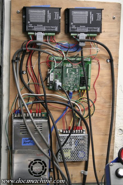
When we last left our intrepid heroes, the electronics for the lathe had been
unceremoniously nailed to a random scrap of plywood, which aided the
various changes and rewirings that were done during development,
but didn't exactly look terribly professional.
However, the wiring and drivers and such were now pretty sell sorted,
so it was time to set it all up properly inside a good enclosure, that
would both protect and organize it better.
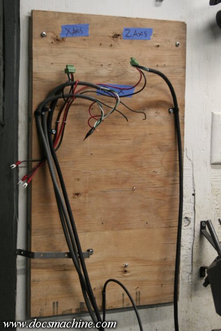
The first step of that, of course, was to tear it all apart.
Hopefully I can remember where all those wires went.
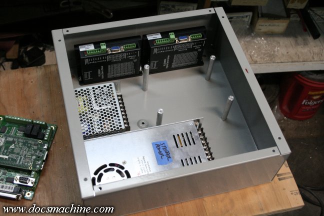
I found this enclosure at the local electrical supply shop, and it turned out to be identical to the one used
in the original control setup. I was hoping to find one with a hinged door/cover, but this one will do fine.
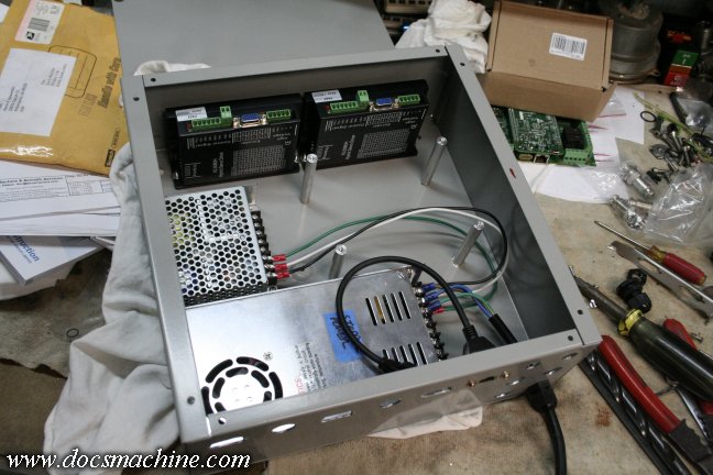
I had to play a bit of 'Tetris' to get everything to fit, keeping in mind wire clearances and such.
The final fix that let everything fit nicely was putting the Acorn board on 2.25" standoffs that I made,
which will let the cords and wires pass behind the board, allow clearance for the Ethernet cable,
and keep the board up front where the status LEDs can be easily seen.
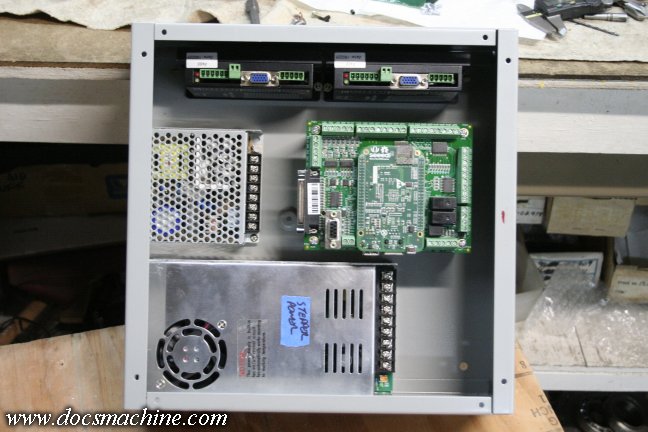
It's a little tighter than I'd have liked, and I'll have to watch the temps when I get it back up and running.
I may need to cut some vents and maybe even add a small fan, but we'll see what happens first.
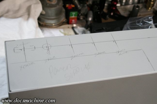
I wanted all the cords and connections at the bottom of the case, as the whole controller will likely
remain hung on the wall behind the lathe. Marking out the 'clear' area on the bottom panel,
I laid out the various connections and ports- two stepper connections, three encoders,
at least two limit switches, the ethernet socket and of course a 110VAC line.
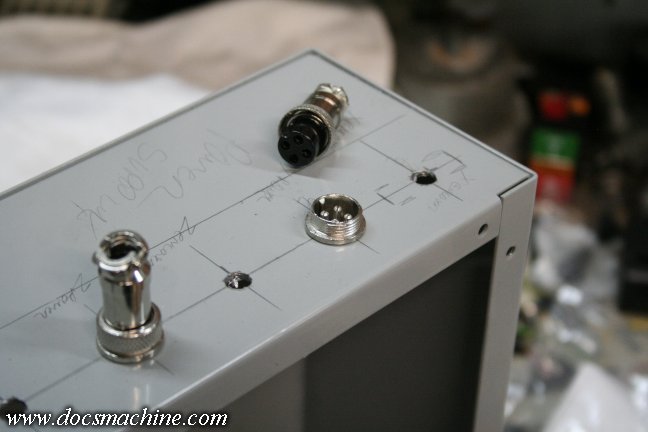
For the stepper connections, I'll be using the ubiquitous GX16 Aviation plugs.
The three encoder connections will be standard DB9 panel-mount ports.
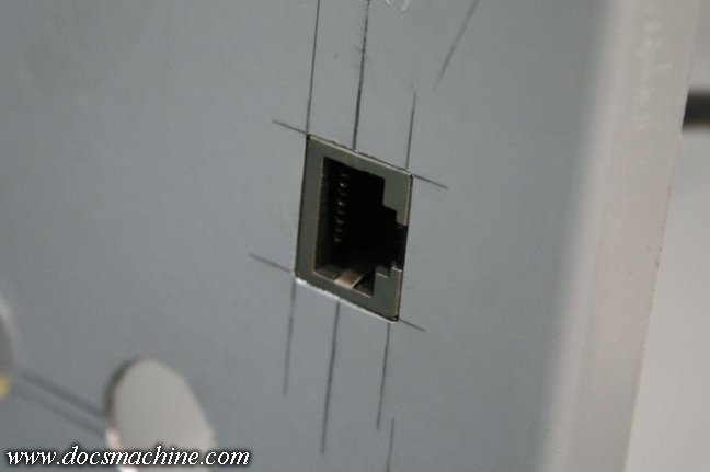
For the ethernet connection, I found this short, shielded extension cable with a flush-mount
female end designed to be bolted to a bulkhead.
For the rest of the connections, I simply drilled round holes, so the cables will pass directly through,
held by a strain relief, and will be connected directly to the electronics. Of the six 'extras', one,
shown, is the 110VAC-in line, at least two will be axis limit switches, and one the E-stop.
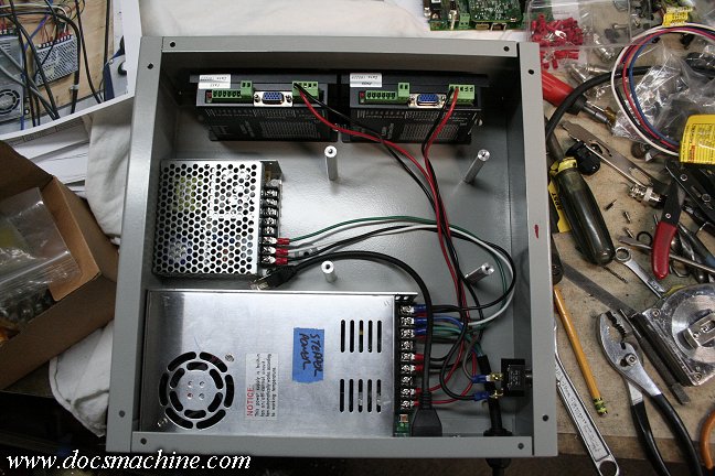
Time to start wiring it proper. The 110VAc input line gets a power switch on the right, which will shortly
get a guard to help prevent accidental shutoffs, the 110 is branched off the main power supply to feed
the driver-signal and Acorn board power supply, and 24V is run up to the drivers.
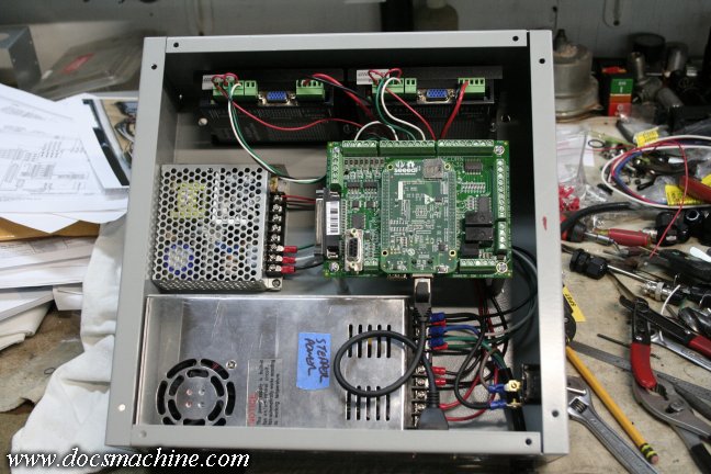
With that done, the Centroid board could be installed, the ethernet port connected,
and the step/direction connections to the drivers made. Next up, some solderin'!
All text, photos and graphics
Copyright 1998- 2018, Doc's Machine & Airsmith Services. All Rights
Reserved.
Information contained in
these pages is for reference and entertainment
purposes only. Our methods are not always the best,
quickest, safest, or even the correct ones. It's up to you to know how
to use your own machines and tools.
Keep your fingers away from the spinny blades o' death and you should
be all right.