[
Return to Main Page ] [
Return to Projects Index
] [
Doc's Machine & TWB Store] [
Contact Us ]
[
The Whiteboard Webcomic
]
Saving a 1943 Springfield Engine Lathe, Part 3:
After the successful test of the headstock and motor, it was finally time to start taking things apart. Most of these photos were taken
simply to record what the parts were and where they went- I have no manual, of course, and this badboy is an order of magnitude more
complicated than the little lathes. While I didn't have to dismantle the headstock (whew!) most everything else got taken pretty down
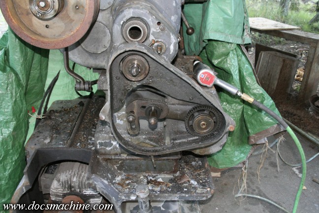
pretty thoroughly. First up was the geartrain from the spindle and dog-clutch, to the quickchange threading box.
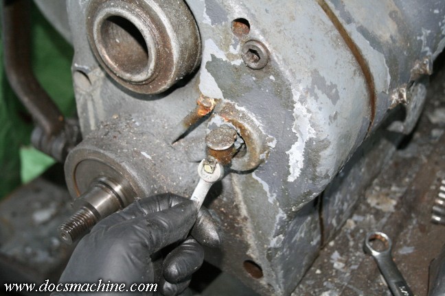
Under that was the dog-clutch housing; this grease cup goes to the idler wheel axle, and the long one to
the left goes to the dog shaft itself. The gear housing is not sealed.
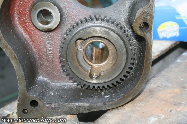
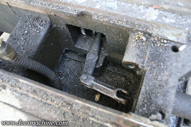
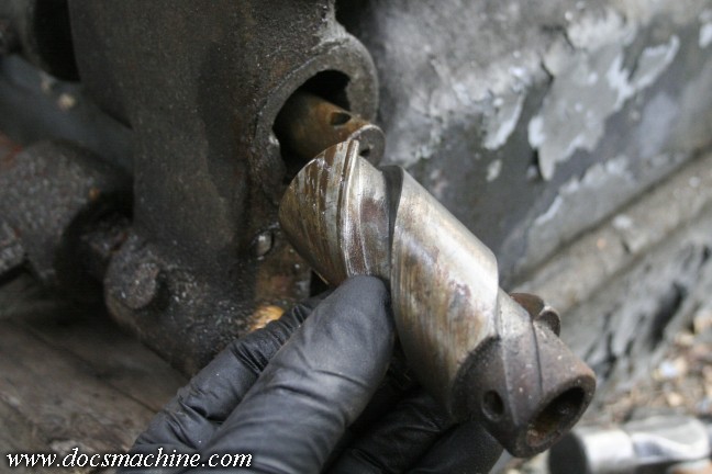
And this is what's known as a single-tooth dog clutch. The shaft which drives it has a matching single large tooth, or "dog",
and is allowed to slide into and out of engagement. The carriage has a rod, with sliding, adjustable stops specifically for this clutch.
When the carriage hits the stop collar, the rod is pushed over slightly, and a linkage disengages the geartrain. If you're simply turning a part,
you can have the feed stop automatically at a certain point, or if you're threading, the feed will also disengage at a certain point.
The working edges are worn somewhat, but not badly, considering the machine is over seventy years old.
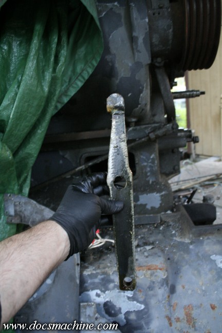
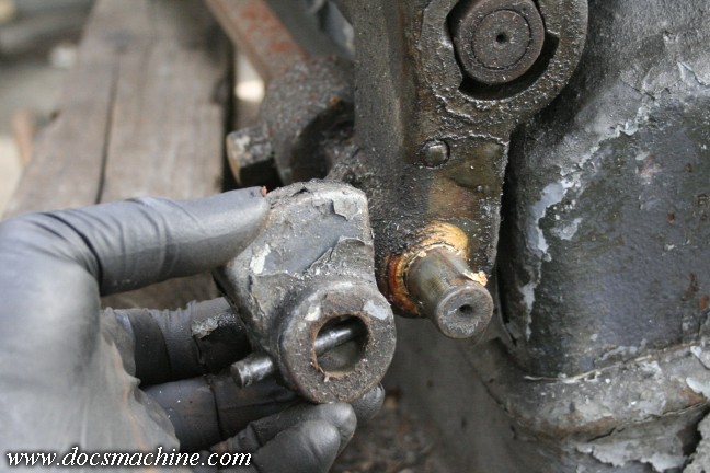
This lever, which had to be extracted out of an access hole in the back of the bed casting, is part of the engage/disengage linkage.
It appears that at some point the original (probably cast) part was broken or lost, and replaced with this somewhat rough but functional
fabricated steel weldment. No indication on when it might have been replaced- it could be a forty year old repair. Who knows?
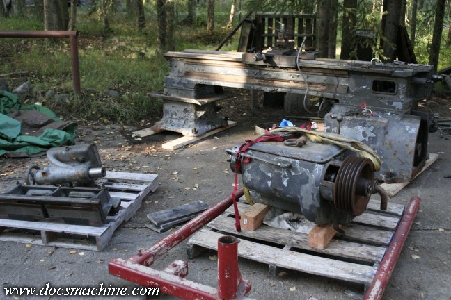
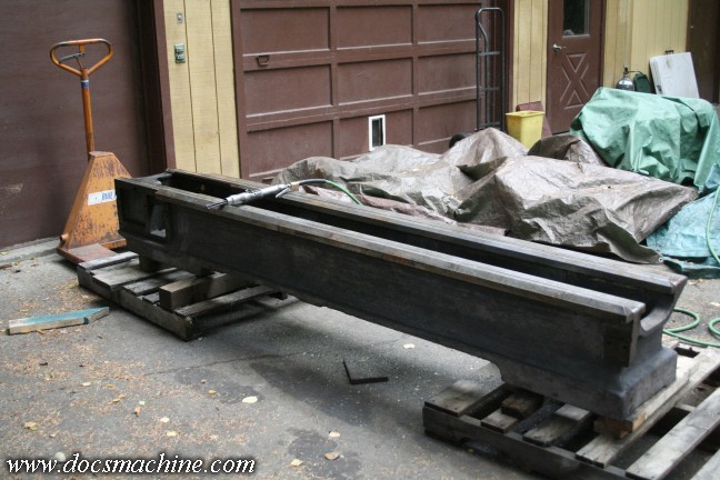
Anyway, with some help and a somewhat overstressed engine lift, we got the headstock off and down safely.
That bloody thing must weigh 1,500 pounds all by itself- my lift had a hell of a time picking it up.
Inside the bed, under the headstock, was this linkage; The open yoke connects to the steel linkage shown before,
and the pivoting arm rides on a sliding collar in the quickchange gearbox. The flexible pipe to the left is where the oil drains
down from the headstock into the sumps in the base casting. This entire area was 6" deep in chips when I got the machine-
so deep they'd started to spill into the threading gearbox through the linkage hole. I didn't want to try any of the
feeds when I was testing everything, for fear of the chips damaging the gears.
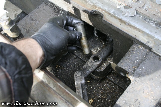
The linkage pivots on this simple stub shaft. Once lifted out, the linkage can be removed.
Now, that stop rod I was talking about? Most home-shop and hobby size lathes have just one rod going across the front of the bed,
to drive the carriage; a combination leadscrew and drive rod. It usually has threads- as a leadscrew needs- and a slot so that a keyed
spool can drive off of it for fine feeds. This Monster, however, has four rods. A leadscrew, a separate slotted drive rod,
a clutch-engagement rod, and the feed/threading stop rod. The bottommost one was the clutch rod, which,
out at the tailstock-end support, had this detent to keep it in position.
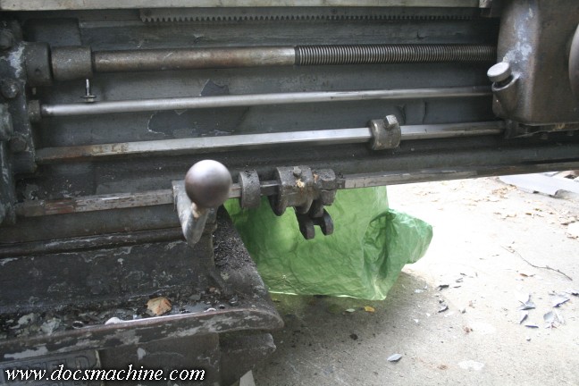
The tailstock end of the feed stop rod is supported by this cool-looking doodad as part of the disengagement mechanism.
The carriage has a lever on it to engage and disengage the dog clutch. The lever is a simple up-and-down motion; this high-helix
fast-action double-lead thread turns that rotary motion into a left-right movement, to slide the dog clutch into or out of engagement.
The spool is a finely machined steel part, and it rides in poured babbit in the rod support. Fortunately it's all in good shape.
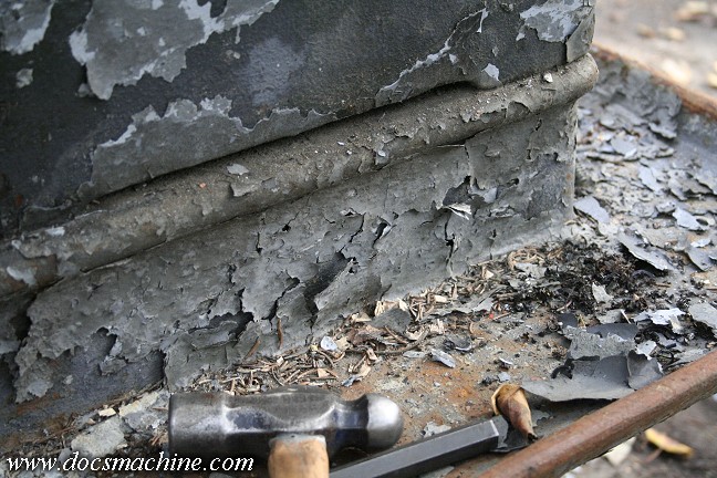
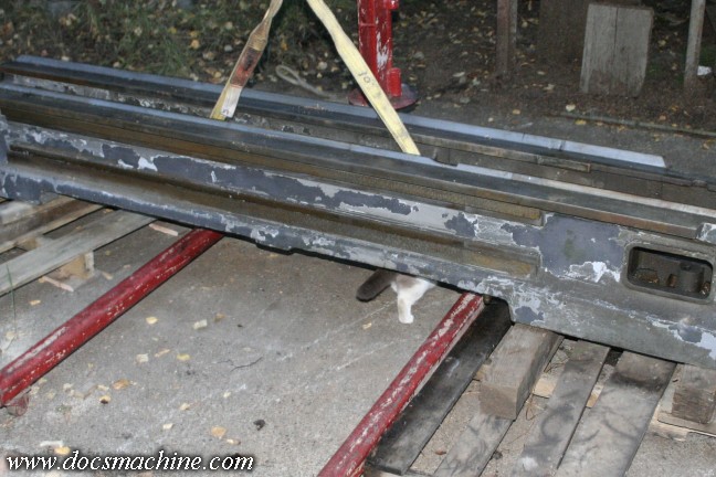
A quick photo of some of the many layers of self-removing paint. The darkest grey appears to be the original
color, with a much lighter layer on top of that, and at least one coat of yet another grey on top.
The aforementioned four operating rods. Again, the top is the leadscrew, used only for threading;
the second from top is a keyed drive rod, used only for drive for turning and facing; Second from the bottom is the
dog-clutch rod, which has three positions, forward, neutral and reverse; and at the bottom is the clutch engagement rod.
The lever shown here is fixed, while a second rod travels with the carriage. The support, in the middle of the
photo, has been broken and repaired... and then broken again.
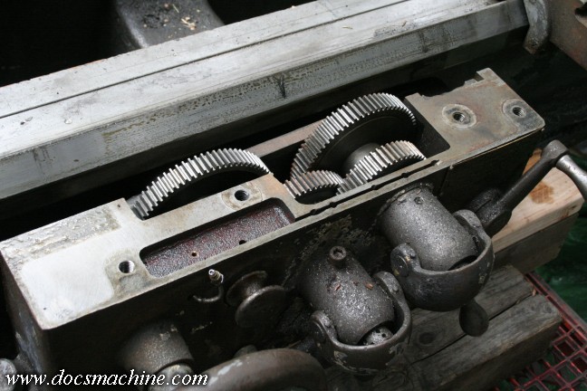
Once all four rods were removed, I could finally disconnect the apron from the carriage and remove
it as well. I was happy to find there were no broken or damaged gears, no cracks, no missing teeth, etc.
With the headstock, carriage, apron, gearbox and tailstock out of the way, I was able to unbolt the
bed from the bases. The headstock base had two of the bolts actually inside the oil sumps.
Shopcat Mk III helped ensure quality work. :)
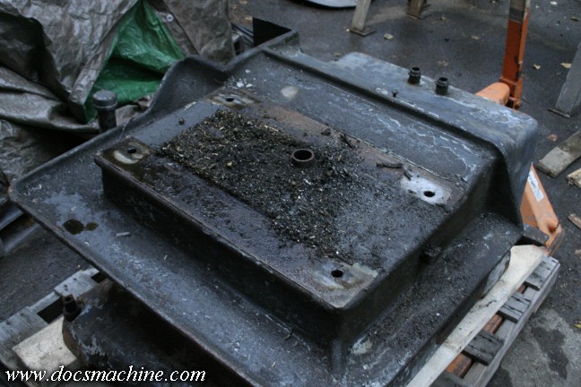
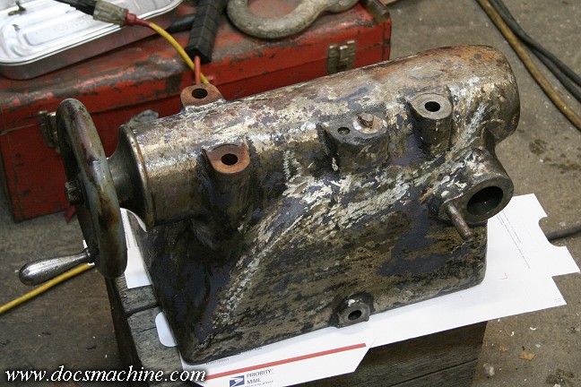
That sump is closed by a sheetmetal cover that is screwed into place. That round port is where the
flexible metal drain tube leads down from the headstock
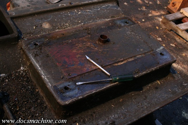
It was a simple matter to scrape away some of the accumulated crud, carefully dig out the slots to the screws,
and remove them. There's a gasket underneath, but it's more to keep dust and grit out than keep oil in.
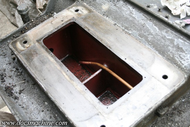
And there's the inside of the sumps. It's separated into two portions; the oil drains down into the right one
(in the foreground) and spills over the top into the second. That gives the oil a little time to settle, in case there's any
gunk or grit in it. Fortnately the sumps were quite clean, with only a slight haze of a nonmetallic, nonmagnetic
black smut. The chambers are painted with Glyptal, a paint specifically used to seal iron castings.
The copper pipe is the pickup line that eventually leads up to the oil pump.
And finally, we're starting to prep the castings. I used a needle scaler to remove most of the paint, leaving behind
only a little of the original filler layer. The scaler was perfect for the job, but it was still tedious, dirty work.
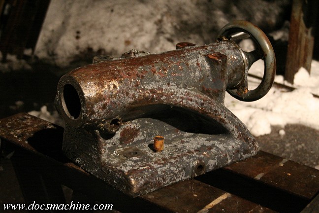
The tailstock got mostly disassembled, hit with degreaser, paint stripper, and the Hotsy pressure washer.
With the paint gone, you can see where somebody went over it with a grinder, to somewhat smooth out
the casting prior to paint. Just the mostly-empty casting is huge, at about 200 pounds.
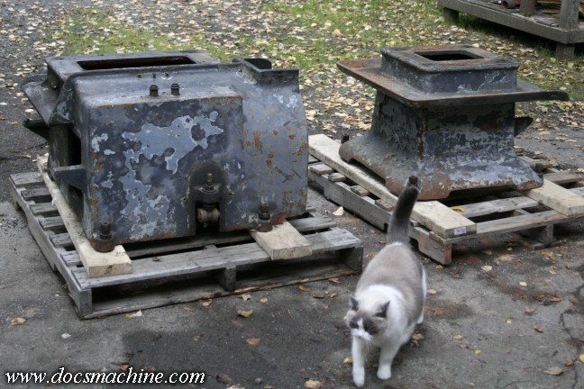
The base castings also got a pressure wash and a going-over with the needle scaler.
The cat, however, remains unimpressed.
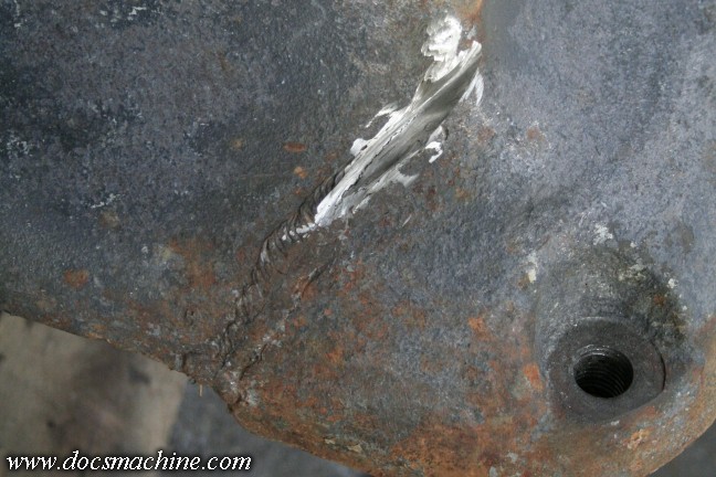
On the near side left foot of the headstock base, I found this crack, that had already been repaired once. The repair had
cracked again, so I began grinding it out in order to weld it up as best I can with more of the Muggy rod.
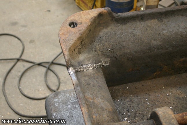
t was slow going, but I eventually got both sides welded up, and the outside smoothed down.
Here's hoping it holds.
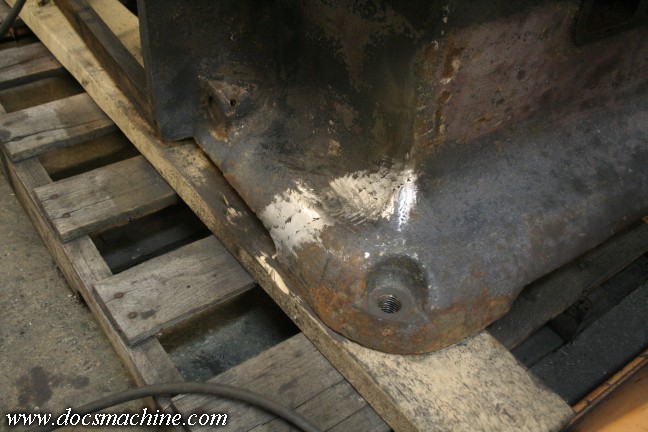
The repair's not invisible, but it's at least stronger than it was. And at this point, I was
ready to start painting, and begin the long process of reassembly.
All text, photos and graphics
Copyright 1998- 2017, Doc's Machine & Airsmith Services. All Rights
Reserved.
Information contained in
these pages is for reference and entertainment
purposes only. Our methods are not always the best,
quickest, safest, or even the correct ones. It's up to you to know how
to use your own machines and tools.
Keep your fingers away from the spinny blades o' death and you should
be all right.